방사형 튜브 히터는 밀폐된 금속 튜브 내부에서 연료를 연소시키고 그 열 에너지를 그 아래의 물체, 사람 및 바닥에 직접 방출하여 따뜻함을 생성하는 가스 연소 적외선 가열 시스템입니다. 건물의 전체 공기량을 데우는 강제 공기 유닛 히터와 달리 복사 튜브 히터는 단단한 표면에 도달할 때까지 직선으로 이동하는 적외선...
READ MOREThe fundamental difference between a radiant tube and a convection tube lies in how heat is transferred from the tube to the surrounding process or load. A radiant tube transfers heat primarily through thermal radiation — electromagnetic energy emitted from the tube's hot outer surface directly to the workpiece or furnace atmosphere without requiring contact or fluid movement. A convection tube, by contrast, transfers heat primarily through forced or natural convection — a fluid (gas or liquid) flowing over or through the tube picks up thermal energy and carries it to the target area.
In industrial furnace and heat treatment applications, this distinction has major practical consequences: radiant tubes are used where the workpiece must be heated in a controlled or protective atmosphere, where the heating source must be isolated from the furnace space, or where very high temperatures are required. Convection tubes are used where uniform bulk heating of a gas or liquid stream is the primary objective, and where direct flame or radiation contact with the process fluid is not required or not desired. Both tube types serve essential roles in industrial thermal processing, but they operate on different physical principles and are engineered for different applications.
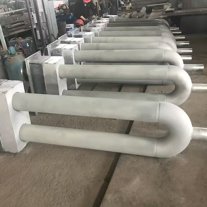
A radiant tube is a sealed, self-contained heating element in which the heat source — either an electric resistance element or a combustion flame — is enclosed inside a protective outer tube. The outer tube surface heats up and emits thermal radiation into the surrounding furnace chamber, heating the workpiece or furnace load without any direct contact between the combustion products (or electrical elements) and the furnace atmosphere.
Electric radiant tubes consist of an inner heating element (the tube core) housed within a sealed outer protective tube. The heating element is available in several configurations to suit different power densities and installation requirements:
The resistance wire materials are selected for high-temperature oxidation resistance and stable electrical properties: nickel-chromium (Ni-Cr) alloys for applications up to approximately 1100°C, and iron-chromium (Fe-Cr) alloys for high-temperature applications extending to 1300°C or above. The surface load of the heating element is designed at a conservative ≤1 W/cm² to ensure long element service life without hot spots or premature failure. Single-tube power ratings range from 3 kW to 60 kW, and the operating temperature of the heating element ranges from 500°C to 1300°C depending on the application.
Gas-fired radiant tubes use a burner at one end of the outer tube to combust fuel (natural gas, LPG, or hydrogen) inside the tube. The combustion gases flow through the tube interior and exit at the other end (or are recirculated), heating the outer tube wall to temperatures typically in the range of 900°C to 1050°C. The outer tube then radiates heat into the furnace chamber. Gas-fired radiant tubes are favored when large heating capacities are required and where the economics of gas combustion versus electricity favor gas heating.
The outer protective tube of a radiant tube is the element that directly faces the furnace environment and must withstand high temperatures, thermal cycling, and the furnace atmosphere chemistry. Three manufacturing methods produce the outer protective tube:
Common outer tube materials include heat-resistant stainless steels (310S, 314, 330), nickel-chromium-iron alloys (alloy 600, 601, 625), and for the highest temperature applications, cast alloys based on nickel-chromium-niobium systems that maintain adequate strength above 1000°C.
A convection tube is a tube through which a process fluid (gas, liquid, or steam) flows while being heated (or cooled) by the surrounding medium. The heat transfer occurs at the tube wall — heat moves through the tube wall from a hot external medium to a cooler internal fluid (or vice versa in cooling applications). The dominant mechanism is convection: forced flow of the process fluid inside the tube creates a velocity boundary layer at the tube wall, and heat passes through this layer by convective heat transfer. External heating of the tube may itself occur through combustion, radiation, steam jacketing, or electrical heating.
In petroleum refinery heaters, petrochemical crackers, and process furnaces, the convection section sits above the radiant section. Hot flue gases rising from the burners pass over banks of convection tubes, transferring heat to the process fluid flowing inside the tubes by convection rather than radiation. The flue gases entering the convection section are typically at 700°C to 900°C and leave at 200°C to 450°C, with the temperature drop representing heat absorbed by the process fluid. Extended surfaces (fins) are commonly added to the outside of convection tubes to increase the heat transfer surface area and improve the relatively lower convective heat transfer coefficient compared to radiation.
Shell-and-tube heat exchangers are the most common industrial convection tube application. Process fluid flows through the tubes while a heating or cooling medium flows around the tubes in the shell. Heat transfers from the hotter stream to the cooler stream through the tube wall. The tube wall in a heat exchanger application must maximize heat conductivity and minimize thermal resistance — typically achieved with thin-walled carbon steel, stainless steel, copper, or titanium tubes depending on the process chemistry. Tube outside diameters in industrial heat exchangers commonly range from 19 mm to 50 mm, with wall thicknesses of 1.5 mm to 3.5 mm.
In water-tube boilers, water flows inside the tubes and is heated by combustion gases outside — a convection-dominated process in the economizer and superheater sections. The convection mechanism is essential for extracting residual heat from combustion gases that have already given up most of their radiant energy in the radiant section of the boiler. Boiler convection tube materials must withstand both the internal water/steam pressure (typically 1 to 30 MPa) and the external flue gas temperature while maintaining corrosion resistance to both environments.

To fully understand the difference between radiant and convection tubes, it is important to understand the underlying heat transfer physics that defines each type's capabilities and limitations.
Thermal radiation is electromagnetic energy emitted by any object with a temperature above absolute zero. The power emitted per unit area follows the Stefan-Boltzmann law: Q = εσT⁴, where ε is the emissivity of the surface, σ is the Stefan-Boltzmann constant (5.67 × 10⁻⁸ W/m²·K⁴), and T is the absolute temperature in Kelvin. The T⁴ dependence means that radiation heat transfer increases very steeply with temperature — doubling the absolute temperature increases radiant heat output by a factor of 16. This makes radiation the dominant heat transfer mechanism at high temperatures (above approximately 700°C), explaining why radiant tubes are the standard solution for high-temperature industrial furnaces. Radiation does not require a medium — it propagates through vacuum or transparent gases, which is why radiant tubes can heat workpieces through furnace atmospheres without convection or conduction.
Convective heat transfer depends on the bulk motion of a fluid carrying thermal energy. The convective heat transfer rate is described by Newton's Law of Cooling: Q = h × A × ΔT, where h is the convective heat transfer coefficient, A is the heat transfer surface area, and ΔT is the temperature difference between the surface and the fluid. Unlike radiation, convective heat transfer varies linearly with temperature difference rather than as T⁴, making it less powerful than radiation at extreme temperatures but more controllable and predictable at moderate temperatures. The heat transfer coefficient h depends strongly on fluid velocity, fluid properties (density, viscosity, thermal conductivity), and tube geometry — which is why fins, turbulators, and high fluid velocities are used to enhance convection tube performance.
The relative importance of radiation versus convection depends strongly on the temperature level:
Beyond their heat transfer mechanisms, radiant tubes and convection tubes differ fundamentally in their structural design, material requirements, installation orientation, and engineering constraints.
| Parameter | Radiant Tube | Convection Tube |
|---|---|---|
| Primary function | Contain heat source; emit radiation into furnace | Carry process fluid; transfer heat to/from it |
| Typical operating temperature | 500°C–1300°C (element); 700°C–1100°C (outer tube) | 50°C–900°C depending on application |
| Tube wall design priority | High-temperature strength, oxidation resistance, emission | Thermal conductivity, corrosion resistance, pressure rating |
| Typical materials | Heat-resistant alloys: 310SS, alloy 601, 625; cast Ni-Cr alloys | Carbon steel, stainless steel, copper, titanium, alloy steel |
| Internal fluid | Heating element (electric) or combustion gas (gas-fired) | Process fluid: oil, gas, water, steam, chemical |
| External medium | Furnace atmosphere; space between tube and workpiece | Flue gas, shell-side fluid, furnace atmosphere |
| Wall thickness | Heavier wall — high-temp strength; not pressure-bearing | Thinner wall optimized for conductivity + pressure rating |
| Surface finish / features | Smooth outer surface for uniform radiation emission | Fins, grooves, or rough surfaces to enhance convection |
| Service life (industrial) | 1–3+ years depending on furnace type and temperature | 5–25+ years with proper material selection and fluid control |
Service life is one of the most practically significant differences between radiant tubes and convection tubes in industrial applications — and the comparison is not straightforwardly in favor of one type over the other. Each type ages through different degradation mechanisms suited to its very different operating conditions.
Radiant tubes operate at extreme temperatures and in thermally cycling environments, making them inherently shorter-lived than convection tubes. The outer protective tube degrades through oxidation and scale formation at the outer surface, carburization or nitridation from the furnace atmosphere, thermal fatigue from temperature cycling, and creep deformation under its own weight at sustained high temperature. For electric radiant tubes, the inner resistance wire element is additionally subject to electrical degradation, hot spot formation, and mechanical fatigue from differential thermal expansion.
Typical electric radiant tube service lives by furnace type are:
These service lives represent guaranteed minimum expectations for quality-manufactured radiant tubes; actual service life frequently exceeds these figures when furnace temperature control is good, atmosphere chemistry is properly managed, and the tube is rated appropriately for its application.
Convection tubes generally achieve longer service lives than radiant tubes because they operate at lower temperatures and are not subjected to the same extreme thermal cycling. However, convection tube degradation is driven by different mechanisms: corrosion from the process fluid chemistry (both internal and external), erosion from high-velocity particulate-laden fluid streams, fouling and scaling that reduces heat transfer efficiency and increases tube wall temperature, creep at the highest temperature locations, and thermal shock from process upsets or emergency shutdowns.
In well-designed and properly operated process heaters and heat exchangers, convection tube service lives of 10 to 25 years or more are common when material selection is appropriate for the process chemistry and operating conditions. Shorter service lives occur when corrosion rates are underestimated, when process upsets cause temperature excursions beyond material limits, or when fouling is allowed to progress to the point where tube wall temperatures exceed design limits.
Understanding which tube type is appropriate for a given application requires matching the heat transfer mechanism, temperature range, and process requirements of the application to the fundamental characteristics of each tube type.
In many industrial fired heater and furnace systems, radiant tubes and convection tubes operate within the same overall unit but in different sections, each exploiting the heat transfer mechanism most suited to the local temperature level and process requirements. This combination is one of the most important concepts in fired heater design.
In a typical petroleum refinery process heater:
The transition from radiant to convection heat transfer as the flue gas temperature drops through the system illustrates why both tube types coexist in the same fired heater — the high-temperature radiation-dominated zone and the lower-temperature convection-dominated zone each require tubes engineered and positioned for their specific heat transfer mechanism and thermal environment.
The maintenance requirements and failure modes of radiant tubes and convection tubes differ substantially, reflecting their very different operating conditions and the distinct degradation mechanisms that affect each type.
Radiant tubes are consumable components with predictable service lives that require scheduled replacement as part of planned furnace maintenance. Key failure modes include:
Convection tube failures in process heaters and heat exchangers are more often gradual — detectable through monitoring before catastrophic failure — and are managed through inspection programs rather than scheduled replacement:
Choosing between a radiant tube and a convection tube for a given industrial heating application requires evaluating several key criteria. In many cases the choice is determined unambiguously by the nature of the process — but in others, both approaches are technically feasible and the decision depends on efficiency, cost, and operational factors.
방사형 튜브 히터는 밀폐된 금속 튜브 내부에서 연료를 연소시키고 그 열 에너지를 그 아래의 물체, 사람 및 바닥에 직접 방출하여 따뜻함을 생성하는 가스 연소 적외선 가열 시스템입니다. 건물의 전체 공기량을 데우는 강제 공기 유닛 히터와 달리 복사 튜브 히터는 단단한 표면에 도달할 때까지 직선으로 이동하는 적외선...
READ MORE대형 창고, 항공기 격납고 또는 분주한 공장 현장을 관리하는 경우 천장에 설치된 난방 시스템 아래를 걸어가면서 일부 공간은 즉시 따뜻하게 느껴지지만 다른 공간은 온도 조절 장치가 목표 온도를 등록한 후에도 오랫동안 머리 높이에서 여전히 차가움을 유지하는 것을 발견했을 것입니다. 그 차이는 종종 열이 전달되는 방...
READ MORE고온 합금 파이프는 특수하게 제조된 합금(일반적으로 니켈, 크롬 또는 코발트 기반 구성)으로 제조된 금속 튜브로, 구조적 강도를 유지하고, 산화에 저항하며, 표준 탄소 또는 스테인레스강 파이프가 파손될 수 있는 극심한 열에 지속적으로 노출되는 크리프 변형을 견디도록 설계되었습니다. 이 파이프는 작동 온도...
READ MORE방사형 튜브에는 일산화탄소 및 기타 연도 가스를 포함한 연소 부산물을 밀봉된 튜브에서 안전하게 제거하고 적절한 크기의 연도 또는 굴뚝 연결을 통해 건물 외부로 배출하기 위한 전용 배기 시스템이 필요합니다. 연소는 가열된 공간의 야외가 아닌 밀폐된 튜브 내에서 완전히 발생하기 때문에 작동하는 배기 경로는 ...
READ MORE